 |
| Structure Text Programming |

Share Knowledge by writing
Thursday, February 24, 2011
Structure Text Programming
important think that we understand the structure text programming. sometime we use the structure text programming in allen bradley panelview plus to manipulate the instruction and to reduce the plc memory.If you know how to program in any high level language, such as Basic or C, you will be comfortable with Structured Text (ST) programming. ST programming is part of the IEC 61131 standard. An example program is shown in Figure below.
The program is called main and is defined between the statements PROGRAM an END_PROGRAM. Every program begins with statements the define the variables. In this case the ariable i is defined to be an integer. The program follows the variable declarations. This program counts from 0 to 10 with a loop. When the example program starts the value of integer memory i will be set to zero. The REPEAT and END_REPEAT statements define the loop. The UNTIL statement defines when the loop must end. A line is present to increment the value of i for each loop.One important difference between ST and traditional programming languages is the nature of program flow control. A ST program will be run from beginning to end many times each second. A traditional program should not reach the end until it is completely finished. In the previous example the loop could lead to a program that (with some modification) might go into an infinite loop. If this were to happen during a control application the controller would stop responding, the process might become dangerous, and the controller watchdog timer would force a fault.ST has been designed to work with the other PLC programming languages. For example, a ladder logic program can call a structured text subroutine.you can download the modulle about Structure Text Programming from here and i do hope it can useful for you.


Monday, February 7, 2011
Understanding Array Concept
Array: a numerically indexed sequence of elements of the dame data type. An array tag occupies a continguous section of memory in the controller with each element in sequence. Array can have one, two or three dimensions.
Element : a single position within an array.
The elements in the array occupy memory in order. The array always start at 0 and extend to the numberof elements minus 1
an array in the tag windows is shown in the following graphic

An array must be created with the following rules in the mind:
- An array can have up to three dimensions unless it is a part of a structure, where then it can have only one dimensions.
- An array can be of one data type only. Array support the following data type:
Thursday, February 3, 2011
USB-to-Data Highway Plus Cable (USB2DHPLUS)
About the Cable
The 1784-U2DHP USB-to-Data Highway Plus Cable allows a customer to connect a computer to a Data Highway Plus (DH+) network via an unused USB port on the computer. You can also use the cable to connect the computer to PLC-5 processors (except for Classic PLC-5 processors, such as PLC-5/10, PLC-5/12, PLC-5/15, and PLC-5/25) or SLC 5/04 processors.

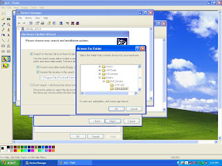
The 1784-U2DHP USB-to-Data Highway Plus Cable allows a customer to connect a computer to a Data Highway Plus (DH+) network via an unused USB port on the computer. You can also use the cable to connect the computer to PLC-5 processors (except for Classic PLC-5 processors, such as PLC-5/10, PLC-5/12, PLC-5/15, and PLC-5/25) or SLC 5/04 processors.
- Insert the end of the cable having the USB connector into an unused USB port on a computer.
You see the Found New Hardware wizard.

- if you do not see the Found New Hardware wizard, go on to step 9
on page 7. Otherwise, continue with the next step. - Select the No, not this time option and click Next.
- Select the Install from a list or specific location option and click Next.
- Select the Search for the best driver option.
- Check only the Include this location checkbox.
- Browse to the location where you saved the 1784_u2dhp.inf file and click OK or from program file >RockwellSoftware>RSLinx.

- Click Next.
- Follow the procedure
- Click Finish.
- DF1 serial 1770-KF2/1785-KE driver for RSLinx Classic Software, Version 2.52 and Earlier.
- Direct using USB2DHPLUS driver listed on RSLinx configure driver for RSLinx Classic Software, Version 2.53 and Later
Wednesday, January 26, 2011
Creating an IP Address On Control Logix
This is the basic standart knowledge, but i want to share it because i ever get little confusing to create one.
Fisrt you must get serial connection to controller before you setup and IP address to the ethernet modulle.Follow this procedure to create DF1 Communication.
- Connect your laptop computer to the ControlLogix controller through the serial port, under t he front cover of its main panel.
 |
| Serial Port on the ControlLogix Controller |
- Start RSLinx Classic program from Start/Programs/Rockwell Software/ RSLinx/RSLinx Classic.
- Click RSWho and If there is no serial connection with a file name including DF1, select Communications/Configure Drivers.
- In the pull down menu labeled Available Driver Types, select RS- 232 DF1 devices and click Add New. Also use this screen to configure other devices, such as Ethernet.
Tuesday, January 25, 2011
Using Ethernet for Industrial Control
Introduction
Ethernet is widely used for information (i.e., office environment) communications today. The technology has availability, familiarity, and cost benefits. Until recently, however, creating an industrial control system using Ethernet was not feasible due to a number of factors, including Ethernet’s lack of determinism, the need for interoperability among devices, and security concerns.
Determinism is the ability to predict when information will be delivered. To guarantee this, an industrial control network must provide scheduled bandwidth (or time slots) that are reserved for time-critical data transfer. Communication over Ethernet, however, is based upon collision detection. If a device attempts to send a message, and that message collides with another message on the Ethernet media, the device backs off and waits to transmit. Thus Ethernet cannot guarantee determinism.
However, recent advances in switch technology have now enabled Ethernet to approach determinism. Switches, unlike traditional bridges and hubs, reduce traffic between the devices attached to their ports. Moreover, the IEEE 802.3 Standard provides for standardized full-duplex operation, which gives a single node - in a point-to-point connection to the switch - full wire concentration. As a result, full-duplex switched Ethernet networks are theoretically able to avoid collisions.
The requirement for device interoperability, the ability of products from different control vendors to communicate with each other, has been answered by the EtherNet/IP (industrial protocol) networking standard. This standard provides interoperability among products from a wide community of automation vendors. It is supported by three major networking organizations: ControlNet International (CI), the Industrial Ethernet Association (IEA) and the Open DeviceNet Vendor Association (ODVA)
Ethernet is widely used for information (i.e., office environment) communications today. The technology has availability, familiarity, and cost benefits. Until recently, however, creating an industrial control system using Ethernet was not feasible due to a number of factors, including Ethernet’s lack of determinism, the need for interoperability among devices, and security concerns.
Determinism is the ability to predict when information will be delivered. To guarantee this, an industrial control network must provide scheduled bandwidth (or time slots) that are reserved for time-critical data transfer. Communication over Ethernet, however, is based upon collision detection. If a device attempts to send a message, and that message collides with another message on the Ethernet media, the device backs off and waits to transmit. Thus Ethernet cannot guarantee determinism.
However, recent advances in switch technology have now enabled Ethernet to approach determinism. Switches, unlike traditional bridges and hubs, reduce traffic between the devices attached to their ports. Moreover, the IEEE 802.3 Standard provides for standardized full-duplex operation, which gives a single node - in a point-to-point connection to the switch - full wire concentration. As a result, full-duplex switched Ethernet networks are theoretically able to avoid collisions.
The requirement for device interoperability, the ability of products from different control vendors to communicate with each other, has been answered by the EtherNet/IP (industrial protocol) networking standard. This standard provides interoperability among products from a wide community of automation vendors. It is supported by three major networking organizations: ControlNet International (CI), the Industrial Ethernet Association (IEA) and the Open DeviceNet Vendor Association (ODVA)
ISO/OSI Protocols
ControlNet
The ControlNet network uses the Common Industrial Protocol (CIP) to combine the functionality of an I/O network and a peer-to-peer network. ControlNet take precedence over program uploads and downloads and messaging. Supports a maximum of 99 nodes.
DeviceNet
DeviceNet is mainly used in industrial and process automation. It is based on CAN technology.
It is a low-cost communication link to connect industrial devices to a network and eliminate expensive hard wiring. Power and communication supplied over a 4-wire bus. Supports up to 62 devices on the same bus network.
ModBus
ModBus is an open, serial communication protocol based on the master/slave architecture. The bus consists of a master station, controlling the communication, and of a number of slave stations.
MODBUS is an application layer messaging protocol, positioned at level 7 of the OSI model, that provides client/server communication between devices connected on different types of buses or networks. MODBUS is used to monitor and program devices; to communicate intelligent devices with sensors and instruments; to monitor field devices using PCs and HMIs. MODBUS is an ideal protocol for RTU applications where wireless communication is required.
The ControlNet network uses the Common Industrial Protocol (CIP) to combine the functionality of an I/O network and a peer-to-peer network. ControlNet take precedence over program uploads and downloads and messaging. Supports a maximum of 99 nodes.
DeviceNet
DeviceNet is mainly used in industrial and process automation. It is based on CAN technology.
It is a low-cost communication link to connect industrial devices to a network and eliminate expensive hard wiring. Power and communication supplied over a 4-wire bus. Supports up to 62 devices on the same bus network.
ModBus
ModBus is an open, serial communication protocol based on the master/slave architecture. The bus consists of a master station, controlling the communication, and of a number of slave stations.
MODBUS is an application layer messaging protocol, positioned at level 7 of the OSI model, that provides client/server communication between devices connected on different types of buses or networks. MODBUS is used to monitor and program devices; to communicate intelligent devices with sensors and instruments; to monitor field devices using PCs and HMIs. MODBUS is an ideal protocol for RTU applications where wireless communication is required.
Sunday, January 23, 2011
Find and Fix I/O Problems
Diagnostic digital modules detect faults and report back.
System designers and end users want to minimise the time it takes to find and fix field device and power supply problems. Using Rockwell Automation FLEX I/O eliminates long wiring runs and reduces terminations per point. But monitoring the condition of I/O and identifying the source of any system failure can be a challenge. Detecting open wire, short circuit and reverse polarity of external power can be tough if you're not right next to the device.
New FLEX I/O diagnostic digital modules (1794-IB16D and 1794-OB16D) detect such faults and report them back to the controller. Once there, they can be monitored via operator panels or a human machine interface (HMI) located remotely.
The FLEX diagnostic modules detect faults such as open/missing input or output field devices or wiring, shorted output field devices, shorted input or output wiring and reverse polarity of user power supply wiring. While they do not check for the presence of the user-supply voltage, this is most easily done by directly wiring the supply voltage to an input channel.
System designers and end users want to minimise the time it takes to find and fix field device and power supply problems. Using Rockwell Automation FLEX I/O eliminates long wiring runs and reduces terminations per point. But monitoring the condition of I/O and identifying the source of any system failure can be a challenge. Detecting open wire, short circuit and reverse polarity of external power can be tough if you're not right next to the device.
New FLEX I/O diagnostic digital modules (1794-IB16D and 1794-OB16D) detect such faults and report them back to the controller. Once there, they can be monitored via operator panels or a human machine interface (HMI) located remotely.
The FLEX diagnostic modules detect faults such as open/missing input or output field devices or wiring, shorted output field devices, shorted input or output wiring and reverse polarity of user power supply wiring. While they do not check for the presence of the user-supply voltage, this is most easily done by directly wiring the supply voltage to an input channel.
Saturday, January 22, 2011
Adding I/O to ControlLogix Online
Installing I/O to a running controller reduces downtime and expands functionality.
Manufacturers need to update their equipment to increase efficiency, adapt to changing product or process needs, and keep up with regulations. However, many continuous process control applications must run for years without scheduled downtime because shutting down a line leads to significant product loss and lengthy start-up procedures.
To help applications deal with high availability requirements, the newest release of RSLogix 5000 software (v15) from Rockwell Automation allows users to add ControlLogix I/O (Bulletin 1756) to a running Allen-Bradley ControlLogix controller. The new I/O can be added to the same chassis as the ControlLogix Central Processing Unit (CPU), or in a remote chassis connected via ControlNet or EtherNet/IP.
Prior to v15, to expand the system, I/O spares had to be pre-installed into a ControlLogix system or production had to be stopped. If the new I/O were in a remote chassis connected via ControlNet, users would then need to reschedule the network. In addition, if multiple controllers were using the same ControlNet network as the I/O, users also would need to place these other controllers into program mode to complete the network scheduling changes. This meant that trying to expand a single process could result in having to shut down a whole line or even the whole plant.
Manufacturers need to update their equipment to increase efficiency, adapt to changing product or process needs, and keep up with regulations. However, many continuous process control applications must run for years without scheduled downtime because shutting down a line leads to significant product loss and lengthy start-up procedures.
To help applications deal with high availability requirements, the newest release of RSLogix 5000 software (v15) from Rockwell Automation allows users to add ControlLogix I/O (Bulletin 1756) to a running Allen-Bradley ControlLogix controller. The new I/O can be added to the same chassis as the ControlLogix Central Processing Unit (CPU), or in a remote chassis connected via ControlNet or EtherNet/IP.
Prior to v15, to expand the system, I/O spares had to be pre-installed into a ControlLogix system or production had to be stopped. If the new I/O were in a remote chassis connected via ControlNet, users would then need to reschedule the network. In addition, if multiple controllers were using the same ControlNet network as the I/O, users also would need to place these other controllers into program mode to complete the network scheduling changes. This meant that trying to expand a single process could result in having to shut down a whole line or even the whole plant.
Friday, January 21, 2011
Troubleshooting an Ethernet/IP System
When troubleshooting any EtherNet/IP™ system, you must have a logical order to troubleshooting. The order for each troubleshooting issue is dependent on the details for that issue. This TechTip will list and detail, in order of priority, the troubleshooting steps for EtherNet/IP systems.
When troubleshooting Ethernet/IP systems, there are potentially many possible troubleshooting scenarios. In general, there are three types of problems:
To resolve any of the above problems, you need to know where to look and what to examine. Check all of the following carefully as possible sources of the problem:
When troubleshooting Ethernet/IP systems, there are potentially many possible troubleshooting scenarios. In general, there are three types of problems:
- It does not work at all
Examples: an I/O node is not connected to a switch (missing cable), cannot ping a node, all MSG instruction to a specific Allen-Bradley® 1756-ENBT ControlLogix® EtherNet/IP Module fails. - It works but is too slow
Example: A resource (PC, controller, 1756-ENBT) in the system is overloaded. - It works but fails intermittently
Examples: The ControlLogix controller outgoing unconnected message buffer is being exceeded, Noise is causing an I/O connection to be lost.
To resolve any of the above problems, you need to know where to look and what to examine. Check all of the following carefully as possible sources of the problem:
- slow PC or slow application running on the PC
- node configuration (IP address, etc.)
- congested network (lots of traffic such as broadcast)
- slow network (satellite or frame relay)
- misconfigured switch or router
- Logix controller resources
- controller processing capability (5550, 5555, 5563)
- timeslice for communications
- cached message queue (32 max)
- unconnected outgoing buffers (40 max) - insufficient processing capability in an ENBT module
- duplicate IP addresses
- defective Ethernet network hardware (e.g., cable, switch port, or ENBT module)
- web server diagnostics or RSLinx® diagnostics
Thursday, January 20, 2011
Configuring an SLC 5/05 Controller's Ethernet IP Address with the BootP Utility
Configuring the IP address for an SLC 5/05 controller can be accomplished in one of two ways, with a serial cable or the BOOTP Server Configuration utility in RSLinx software version 2.42 or later. The BOOTP utility is the less common of the two methods, but it is a convenient tool if the serial port or serial cable is not available.
This Tech Tip Provides instructions on configuring the IP address for an SLC 5/05 controller with the BootP utility. The steps include:
Locating the MAC address for the SLC 5/05 controller.
The MAC address is the hardware address that uniquely identifies each node on the Ethernet network. It is pre-assigned at the factory and is not configurable. Before configuring the IP address for the SLC 5/05 controller, you need to locate and record the MAC address for your SLC 5/05. To do this, use these steps:
This Tech Tip Provides instructions on configuring the IP address for an SLC 5/05 controller with the BootP utility. The steps include:
- Locating the Media Access Control (MAC) address of your SLC 5/05 controller
- Configuring SLC 5/05 Ethernet communications using the BOOTP Server
- Configuring a static IP address
- It is assumed you have an SLC 5/05 connected to a hub or switch and the computer's networking has already been configured.
- Use an IP Address of 192.168.2.2 and a Subnet Mask of 255.255.255.0 for the SLC 5/05 controller. Be sure that the IP Address for the computer is on the same subnet as the SLC 5/05 controller (for example, IP: 192.168.2.3 Subnet: 255.255.255.0).
- If you are not familiar with Ethernet networking, refer to the Microsoft Help section titled, "Configuring TCP/IP" for information on configuring a static IP Address.
- Always consult your network administrator before making changes to your networking configuration.
Locating the MAC address for the SLC 5/05 controller.
The MAC address is the hardware address that uniquely identifies each node on the Ethernet network. It is pre-assigned at the factory and is not configurable. Before configuring the IP address for the SLC 5/05 controller, you need to locate and record the MAC address for your SLC 5/05. To do this, use these steps:
- Remove power from the SLC 5/05 controller and remove the unit from the rack.
- On the bottom left corner of the SLC 5/05 daughter card, locate the small white label printed with a hexadecimal number. The number begins with 00:00:BC.
- Record the number on a piece of paper. This number is unique to your SLC 5/05 controller.
- Insert the SLC 5/05 controller back into the rack and power it up.
Subscribe to:
Posts (Atom)